|
|
| NOT
Gate or Inverter |
|
|
The NOT gate or Inverter is the simplest of all logic gates.
It
has only one input one output. Where the output Y opposite of
the input. The NOT gate is often called inverter because it inverts
the input. |
|
|
|
|
|
|
|
Fig
(b) |
|
|
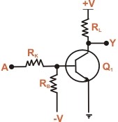
| Fig (a) shows a typical
inverter circuit. When A is connected to ground, the base of
transistor Q1 will become negative. The negative
potential cause the transistor to cut off and large positive
voltage is applied at A, the base of the transistor will become
positive, causing the transistor to conduct heavily. Therefore,
the output voltage is zero. In binary terms, when A = 1,Y =
0. as shows truth table for an inverter. It is clear from the
truth table that whatever the input to the inverter, the output
assumes opposite polarity. If the input is 0, the output will
be 1: if the input is 1,the output will be 0. |
|
| |
Truth
Table |
|
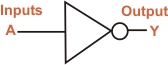
Fig (b) shows the
logic symbol for NOT gate or inverter. Note that small bubble
on the inverter symbol represents inversion. The Boolean expression
for NOT function is
Y =

Note that bar above the input A represents inversion.
If A = 0, then Y =  or Y = 1
If A = 1, then Y =  or Y = 0
 |
|
|